Update:
Unfortunately the JamMan Stereo looper also sends the looped/overdubbed audio to the Rhythm Output which means that after the first audio data is recorded into an empty loop location the Rhythm output will also be outputting the loop audio and the sync circuit won’t sync properly anymore. So the only other source for a sync signal is the TEMPO/STOP LED. I think I’ll just solder a wire to it and route it to the outside of the case and connect it to the sync circuit. The code will need to be changed/simplified a bit.
End update.
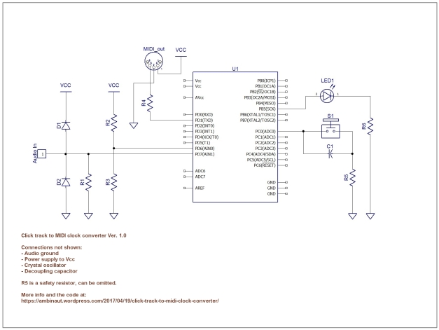
Click track to MIDI clock DIY converter circuit Ver.1.0
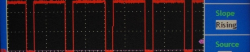
This circuit is designed to generate MIDI clock messages from incoming audio pulses from e.g. a click track, in my case it is the rhythm output of a Digitech JamMan Stereo looper. The audio clicks should be shorter than 150 milliseconds, not overlap each other and preferably with a fast attack. The tempo range is 40 to ca. 240 BPM.
The firmware for the 1.0 version was written for a Atmega328p MCU so it should also work with the m168/88/48 chips. The code came out a bit complex since I wanted to build a circuit with the least amount of components. I have another version of the converter which has simpler and shorter code but has more external components. I might make a blog entry about it later on.
Mode of operation:
At startup the converter waits for the first incoming audio click after which is starts counting and waiting for the second click. At the moment of the second click the converter divides the time between the first and second clicks by 24 and starts sending MIDI clock, i.e. goes into “pulsed” mode.
If the second click is not detected within ca. 1.5 seconds (tempo slower than 40BPM) the converter goes back to the beginning.
The MIDI start switch (press and hold) can be used to send a MIDI start message right before the next audio click, this will set the receiving MIDI device to start playback from the beginning of the sequence therefore syncing the MIDI device with the audio clicks.
If audio clicks stop then the converter goes into “Free Running” mode, i.e. it will continue to send MIDI clock without incoming audio clicks. While in “Free Running” mode the MIDI start switch is not operational.
If audio clicks resume the converter goes back to pulsed mode.
If the tempo changes a reset is needed to re-calculate the tempo.
Circuit info:
The circuit diagram does not have all connections shown. You’ll have to connect the common/ground from the audio device to the ground of the MCU, Arduino or whatever board you have, in my case it’s a Arduino Pro Mini with a m328p MCU and a 16MHz crystal. You’ll also have to connect Vcc to a 5V power supply and add a 16MHz crystal oscillator plus the capacitors and maybe a decoupling if you’re building the circuit from scratch.
Components:
D1 and D2 – Clamping diodes,. I used 1n4148.
R1 – Pull Down resistor. 10K but you can try other values
R2 and R3 form a voltage divider.
R2 – 10K Ohms
R3 – 300 Ohms (can be replaced with a potentiometer)
R4 – 220 Ohms, current limiting.
R6 – Current limiting resistor. Value depends from the LED type.
S1 – tactile switch
C1 – debouncing cap, 0.1uF
R5 – safety resistor, can be left out of the circuit.
Get the code here: https://github.com/ambinaut/click-track-to-MIDI-clock-converter
Here’s a video of an almost identical circuit. The difference is the MCU and that it uses more components. Click track to MIDI clock demonstration

Seems to work well in the video! Are you taking orders for these?
Hi, can you describe your setup so I could tell if the circuit will work in your case.
Hello, My friend has Korg Volca Sample that I want to take his click track and convert to MIDI for my Pigtronix Infinity. Seems like your circuit would work.?.
Hi,
if the click track are audio signals with sharp attacks and not longer than 150ms then it should work.
best regards