UPDATE: I modified the first circuit to work with the new code that has an interrupt enabled. See the bottom of the page.
I’ve previously posted two circuits for synchronizing the JamMan, one based on Schmitt triggers and another one using a 555 timer.
This time the circuit syncs the JamMan to an external MIDI clock. The circuit is based on an Attiny85 MCU running at 8MHz (internal oscillator) using the SoftwareSerial.h library included with the Arduino IDE. The circuit+code seems to work good with just midi clock data coming in, without too many other types of messages being received simultaneously, i.e. I’m not sure how it will handle a big stream of midi data, if it will be able to properly discern between clock and other messages.
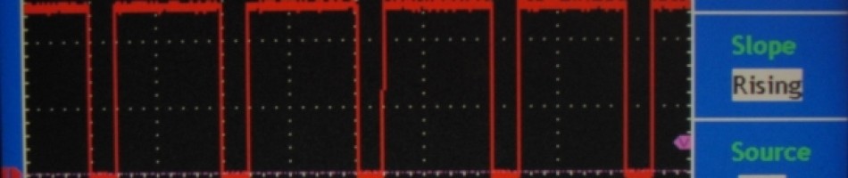
When the circuit detects midi clock messages on the input it will blink the tempo LED every 1/4 note, i.e. every 24th clock message. Pressing the tap tempo switch will send the 1/4 pulses to the JamMan.
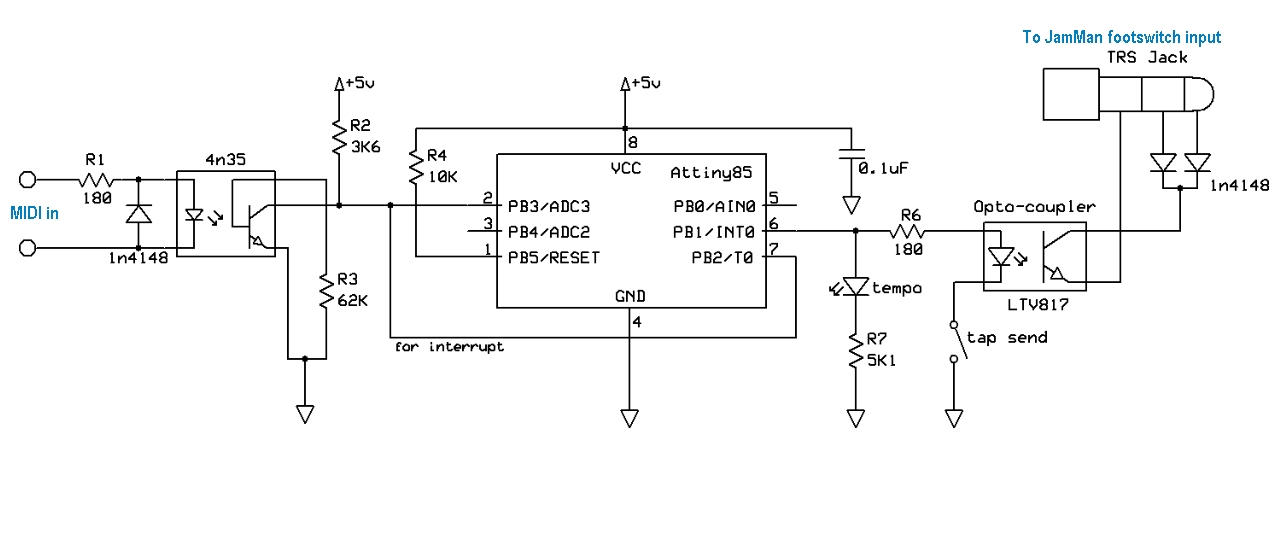
Here’s the 1.0 version of the circuit:

Digitech JamMan stereo looper synchronization to MIDI clock
And the code:
https://gist.github.com/ambinaut/3dfc054652405e5d1872
or:
/* This sketch listens to incoming midi clock messages on port RX and pulses output tempo_pin each quarter note,
i.e. every 24th clock tickWritten for Attiny85 but can be modified for other Atmega, Attiny MCU’s
IMPORTANT! Don’t use pins RX, TX for anything else othar than the SoftwareSerial library
*/#include <avr/io.h> //Include the headers that handles Input/Output function for AVR chips
#include <util/delay.h> //Include the headers that allow for a delay function
#include <SoftwareSerial.h> //Arduino Software Serial library#define F_CPU 8000000UL //Define the speed the clock is running at. Used for the delay.h functions
#define tempo_pin 1 //Physical pin 6, or PB1 on the Attiny85byte midi_msg = 0; //stores incoming midi messages, only 1 byte needed, real time msgs are one byte long
byte clockpulse = 0; //stores current midi clock tick number
unsigned long last_midi_event_time = 0; //time of the last incoming midi eventSoftwareSerial mySerial(3, 4); // RX, TX Physical pins 2, 3
void init_io(void)
{
DDRB |= _BV(tempo_pin); //sets tempo_pin as outputs
PORTB &= ~(_BV(tempo_pin)); //sets the pin to LOW
}int main(void)
{
init_io();
init();
mySerial.begin(31250);while (1) { //endless loop
if (mySerial.available()) {
midi_msg = mySerial.read();
last_midi_event_time = millis();
midi_clk_to_pulse(); //see below
}
//if there’s no more incoming midi for longer than 1000ms, set tempo_pin LOW
else {
unsigned long current_time = millis() – last_midi_event_time;
if (current_time > 1000){
midi_msg = 0xFC; //midi stop message
last_midi_event_time = 0;
midi_clk_to_pulse();
}
}
} //END while (1) – endless (main) loop
}void midi_clk_to_pulse(){
switch(midi_msg) {
case 0xFC: //midi stop message
clockpulse = 0;
PORTB &= ~(_BV(tempo_pin)); //sets tempo_pin to LOW
break;case 0xFA: //midi start message
clockpulse = 0;
PORTB &= ~(_BV(tempo_pin)); //sets tempo_pin to LOW
break;case 0xF8: //midi clock pulse
clockpulse = clockpulse + 1;
switch (clockpulse){
case 1:
PORTB |= (_BV(tempo_pin)); //tempo_pin HIGH
break;case 8:
PORTB &= ~(_BV(tempo_pin)); //tempo_pin LOW
break;case 24: // second quarter begin
PORTB |= (_BV(tempo_pin)); //tempo_pin HIGH
break;case 32:
PORTB &= ~(_BV(tempo_pin)); //tempo_pin LOW
break;case 48: // third quarter begin, middle of the measure
PORTB |= (_BV(tempo_pin)); //tempo_pin HIGH
break;case 56:
PORTB &= ~(_BV(tempo_pin)); //tempo_pin LOW
break;case 72: //fourth quarter begin
PORTB |= (_BV(tempo_pin)); //tempo_pin HIGH
break;case 80:
PORTB &= ~(_BV(tempo_pin)); //tempo_pin LOW
break;case 96:
clockpulse = 0; // resets the clock pulse counter, 96 pulses = 1 measure in 4/4
break; //END case 0xF8:
} // END switch (clockpulse)
break;
} // END switch(midi_msg)
} //END midi_clk_to_pulse()
According to the SoftwareSerial library explanation the Attiny has to run at 8MHz for it to function properly so don’t forget to set the right fuses accordingly. The only thing to take in consideration is that the clock could drift with temperature differences and that might affect serial communication, perhaps even stop it from reading incoming data correctly. I might do another circuit with an external crystal but then the circuit will have to be changed since you need two pins to connect the external crystal.
Any comments or suggestions are welcome,
have fun!
UPDATE: The new code has a sleep function. If there is no MIDI signal going into the input for longer than one sec the Attiny goes into sleep mode to save power. An interrupt on pin7 disables sleep mode when data starts coming in again.
DigiTech JamMan MIDI sync circuit
The code with the added sleep mode:
/*
This sketch listens to incoming midi clock messages on port RX and pulses output tempo_pin each quarter note, i.e. every 24th clock tick
Written for Attiny85 but can be modified for other Atmega, Attiny MCU’s
IMPORTANT! Don’t use pins RX, TX for anything else other than the SoftwareSerial library
*/
#include <avr/io.h> //Include the headers that handles Input/Output function for AVR chips
#include <util/delay.h> //Include the headers that allow for a delay function
#include <SoftwareSerial.h> //Arduino Software Serial library
#include <avr/sleep.h> // Lib for sleep modes
#include <avr/interrupt.h> //Lib for interrupts
#define F_CPU 8000000UL //Define the speed the clock is running at.
#define tempo_pin 1 //Physical pin 6, or PB1 on the Attiny85
byte midi_msg =0;//stores incoming midi messages, only 1 byte needed, real time msgs are one byte long
byte clockpulse =0;//stores current midi clock tick number
unsignedlong last_midi_event_time =0;//time of the last incoming midi event
SoftwareSerial mySerial(3,4);// RX, TX Physical pins 2, 3
void init_io(void)
{
DDRB |= _BV(tempo_pin);//set tempo_pin
PORTB &=~(_BV(tempo_pin));//set the pin to LOW
}
int main(void)
{
init_io();
init();
mySerial.begin(31250);
while(1){//endless loop
if(mySerial.available()){
midi_msg = mySerial.read();
last_midi_event_time = millis();
midi_clk_to_pulse();//see below
}
//if there’s no more incoming midi for longer than 1000ms, set tempo_pin LOW
else {
unsignedlong current_time = millis()– last_midi_event_time;
if(current_time >1000){
midi_msg =0xFC;//midi stop message
last_midi_event_time =0;
midi_clk_to_pulse();
sleep();
}
}
}//END while (1) – endless (main) loop
}
void midi_clk_to_pulse(){
switch(midi_msg){
case0xFC://midi stop message
clockpulse =0;
PORTB &=~(_BV(tempo_pin));//turns tempo_pin off
break;
case0xFA://midi start message
clockpulse =0;
PORTB &=~(_BV(tempo_pin));//turns tempo_pin off
break;
case0xF8://midi clock pulse
clockpulse = clockpulse +1;
switch(clockpulse){
case1:
PORTB |=(_BV(tempo_pin));//tempo_pin HIGH
break;
case8:
PORTB &=~(_BV(tempo_pin));//tempo_pin LOW
break;
case24:// second quarter begin
PORTB |=(_BV(tempo_pin));//tempo_pin HIGH
break;
case32:
PORTB &=~(_BV(tempo_pin));//tempo_pin LOW
break;
case48:// third quarter begin, middle of the measure
PORTB |=(_BV(tempo_pin));//tempo_pin HIGH
break;
case56:
PORTB &=~(_BV(tempo_pin));//tempo_pin LOW
break;
case72://fourth quarter begin
PORTB |=(_BV(tempo_pin));//tempo_pin HIGH
break;
case80:
PORTB &=~(_BV(tempo_pin));//tempo_pin LOW
break;
case96:
clockpulse =0;// resets the clock pulse counter, 96 pulses = 1 measure in 4/4
break;//END case 0xF8:
}// END switch (clockpulse)
break;
}// END switch(midi_msg)
}//END midi_clk_to_pulse()
void sleep(){
GIMSK |= _BV(PCIE); // Enable Pin Change Interrupts
PCMSK |= _BV(PCINT2); // Use PB2 as interrupt pin
ADCSRA &=~_BV(ADEN); // ADC off
set_sleep_mode(SLEEP_MODE_PWR_DOWN); // replaces above statement
sleep_enable(); // Sets the Sleep Enable bit in the MCUCR Register (SE BIT)
sei(); // Enable interrupts
sleep_cpu(); // sleep
cli(); // Disable interrupts
PCMSK &=~_BV(PCINT2); // Turn off PB2 as interrupt pin
sleep_disable(); // Clear SE bit
ADCSRA |= _BV(ADEN); // ADC on
sei(); // Enable interrupts
}// sleep

Hello,
i used some parts of your circuit and code for my own project.
I use an ATTiny45 to read Control Changes and switch two relays, but i had much trouble with reading the midi signal.
The Tiny runs with its internal Oszillator at 8MHz because I need all pins and cant use an external Crystal.
The problem is that the Oszillator isn’t well calibrated by Atmel. It can differs +-10%.
A Control Change command consists of three bytes. There was a 3-5% chance to receive all bytes correct.
Did you ever had issues by receiving the signals?
I had to calibrate the OSCCAL register to trim the internal Oszillator.
Hi,
I’m running the Attiny85 at 5.25V, perhaps that’s why it’s stable. Plus a MIDI Clock message is only one byte long whereas a CC is 3 bytes long. I did not do anything with the OSCCAL register since I did not have to.
I did not have any issues with receiving MIDI data, although I don’t remember if I tested the circuit with an intense flow of data. For now I just send a clock signal to it without any other MIDI messages.
Hey aminaut! Great work!
I’m going to start work on something similar but a bit simpler. Syncing the Jamman with my eurorack modular synth system – the clock signals are usually I think around 3-5V and I have a clock divider and a clock multiplier. Am I right in thinking I could basically put a mini jack socket output in the circuit by the LED tempo output, and that’ll give a voltage pulse? I haven’t measured it yet but presume it may need attenuating. Then I’d like to do things the other way round have a mini jack socket to optocoupler to stereo jack plug for sending tempo through the foot switch input.
Just wondering if you have any tips, thoughts or ideas before I get started since you’ve done all this before?
Thanks! Feel free to email me if you prefer
Marcus
Hi,
– if I understand correctly you want to sync JamMan to the Euro-rack by using the tap tempo input foot-switch input on the JamMan? That’s what my MIDI to tap tempo does, but the JamMan starts to drift out of sync in ca. 2-3 minutes so it needs re-syncing. So a better solution would be to sync the Euro-Rack to the JamMan. I’m almost finished with that circuit and code, will post it soon.
– You can use the LED tempo output, but you have to watch out how much current you’re going to drain, since the opto-coupler might not get enough current to switch on, plus the Attiny85 has limits on how much current it can source.
– “Then I’d like to do things the other way round have a mini jack socket to optocoupler to stereo jack plug for sending tempo through the foot switch input.”
Well that’s exactly what attiny85 circuit above does, or did you want to use it for something else other than the JamMan?
HI, just to confirm?
For Midi Jack? pin4 to 180ohm and pin5 to 1n4148?
is that ok?
Hi,
well the placement of the resistor does not matter, the current will be the same. But ye, in the schematic above the resistor is connected to pin 4 of the midi socket, and the anode of the diode to pin 5.
hi , i tried to upload the second code and it gives me error? the first code is ok ready for uploading ,,
i want to ask? can i use the first code with the second circuit? it will work or not?
i use digispark tiny85 ,with digispark arduino 1.0.4. softwere on mac..
this is the error
sketch_jul25a:89: error: stray ‘\’ in program
sketch_jul25a:39: error: ‘unsignedlong’ does not name a type
sketch_jul25a.ino: In function ‘int main()’:
sketch_jul25a:79: error: ‘last_midi_event_time’ was not declared in this scope
sketch_jul25a:89: error: ‘unsignedlong’ was not declared in this scope
sketch_jul25a:89: error: expected `;’ before ‘current_time’
sketch_jul25a:91: error: ‘current_time’ was not declared in this scope
sketch_jul25a:95: error: ‘last_midi_event_time’ was not declared in this scope
Hi,
these look like type errors. Missing ‘;’ , unsignedlong instead of unsigned long. Also undeclared variables. Are you sure you copied and pasted everything properly? From here:
This file contains bidirectional Unicode text that may be interpreted or compiled differently than what appears below. To review, open the file in an editor that reveals hidden Unicode characters.
Learn more about bidirectional Unicode characters
Attiny85_MIDI_clk_to_tap_tempo_03_ADC_off.ino
hosted with ❤ by GitHub
ok, i solved this with upload, thanks
Hi, i’m having trouble finding the Attiny85 MCU in my contry, is there any other microcontroler that i can use?
Hi, yes you can use other attiny chips like attiny2313, or atmegas atmega8, 16, 328, and many other, but you might have to make some changes to the code. Btw, attiny85 is sold on ebay and tayda electronics: http://www.taydaelectronics.com/attiny85-attiny85-20pu-8-bit-20mhz-microcontroller-ic.html
Hello again, I would liko to know whitch one of the 6 tips you used in the 4n35 and the LTV817 and if that one can be replaced for another one and if so, whitch one. Also I’m having trouble to know what you meant in R2 and R7 whith the number after the “k” in “3k6 and 5k1”.
To know which pins to use you just look at the datasheet: http://www.vishay.com/docs/81181/4n35.pdf
Click to access LTV-817_827_847%28M,S,S_TA1%29.pdf
I guess the 4n35 could be replaced with a 4n36/7 or 4n25/6/7/8 but I don’t remember if the values of R2 and R3 would remain the same or would need to be changed. The LTV817 is a generic, slow opto-coupler, you can use pretty much anything else, pc817, etc…
3k6 means 3600, 5K1 means 5100.
Hi !
Do you make these modifications for others ?
It would be great to have MIDI in my Janman Stereo.
Thanks
Leo
Hi, which modifications? What is others?
Can this also be used to sync a delay to the jamman. I want to record a loop and then use jamman sync to trigger a tap tempo
“I want to record a loop and then use jamman sync to trigger a tap tempo”
Can you describe the chain of equipment, which output goes to which input on which device?
I recently bought a solo xt and i want to connect the jam sync out to an arduino board. The arduino board controls a relay that connects to a zoom g3. I have two wires soldered to the tap tempo button. If those wires connects it has the same effect as when i push the button on the zoom g3.
I already test this with a normal midi clock and i hope that i just have to change the byte midi_start, midi_stop, midi_clock and midi_continue
the arduino sketch is:
int counter = 0;
int output_pin = 6; // set output pin
int inPin = 7;
int val = 0;
byte midi_start = 0xfa;
byte midi_stop = 0xfc;
byte midi_clock = 0xf8;
byte midi_continue = 0xfb;
int play_flag = 0;
byte data;
int buttonState = 0;
void setup() {
Serial.begin(31250);
pinMode(output_pin, OUTPUT);
pinMode(inPin, INPUT);
buttonState = digitalRead(inPin);
}
void loop() {
if((counter == 0) && (val==0)) {
digitalWrite(output_pin, HIGH);
}
if(Serial.available() > 0) {
data = Serial.read();
if(data == midi_start) {
play_flag = 1;
}
if (data == midi_stop) {
counter = 0;
val = 0;
}
else if(data == midi_continue) {
play_flag = 1;
}
else if(data == midi_stop) {
play_flag = 0;
}
else if((data == midi_clock) && (play_flag == 1)) {
Sync();
}
}
}
void Sync() {
if (buttonState == HIGH) {
counter = 0;
val = 0;
}
if((counter == 23) && (val 22) && (val=5)) {
digitalWrite(output_pin, HIGH);
}
else if(counter < 23) {
counter = counter + 1;
digitalWrite(output_pin, LOW);
}
}
@wessel van der burg
so the device chain looks like this?
(my jamman sync circuit) – arduino board – relay – two wires soldered to tap tempo button on the zoom g3
?
Yes
all right, so where does the SOLO XT come into this chain?
the solo xt sends out a jamsync message to the arduino board. Arduino board drives the relay. Relay controls tap tempo.
I don’t have a solo xt but I’ve looked online for info about the SYNC OUT that it has, and it’s not MIDI but rather a proprietary protocol, more about it here: http://fuzzysynth.blogspot.it/2015/06/digitech-jam-man.html
So if you want to use the SYNC output from the SOLO XT to connect it to my JamMan Sync circuit it won’t work, since my circuit needs MIDI clock signals.
hi, thanks for this project, looks like exactly what i need.
question: since i have zero experience with chip programming, i assume the easiest way for me to try this out is to get one of those tiny boards with built-in usb support:
http://www.instructables.com/id/Digispark-DIY-The-smallest-USB-Arduino/
will this work? the pinout looks fine, all necessary pins available, but wouldn’t the circuit on the board interfere somehow with your design?
thanks,
tomas
Hi,
you can use any Arduino board for this, only the code needs to be modified for the specific MCU.
I usually get the cheapest ones from eBay, for under 2 bucks you can get a arduino mini nano micro with a Atmega328 on it, and for like 3 bucks you can get a board that also has a dedicated USB chip on it.
The Digispark board does not have a separate USB chip so you need a programmer for it.
A way to do it is to buy a cheap (under 2 bucks) USBASP programmer and the Digispark board or a Attiny85 chip, build the above circuit and use Arduino IDE to program the chip. It’s easy and there are a lot of tutorials on youtube.
This looks like THE THING for me! I want to sync the Looperman Stereo with Korg Volca Sample’s tempo, will this work? Since I am a complete rookie in this field (electronics, programming, circuits etc.) can you build one for me? Thank you soooo much, I have all the music ideas and concept but no technical knowledge to make it work. Thank you and greetings from Slovenia.
Hi, the above circuit with the attiny can’t be used to sync the two devices.
There is another circuit that NEEDS to be MODIFIED (read update) and will sync any MIDI device with MIDI clock input to the JamMan stereo looper.
At the moment I’m in the process of moving so I can’t build anything.
Best regards
Hi, do you have a components list for the Digitech Jamman Stereo Midi Sync?
I own a Stereo Looper /Phraser Sampler with a similar stereo input for the remote control. I also want to tap in from a Midi Master Clock.
I was looking for a DIY solution so I can combine Live loops ( recording on the Jamman ) with a simple synth sequencer or drum computer.
I am no expert at electronics so a components list would help a lot.
Thanks in advance
Best Regards Thomas
Hi, if you want to convert midi clock messages to tempo taps, then the circuit should work.
You’ll need:
1) 4n35 or similar speed optocoupler for the MIDI input.
2) LT817 or similar for the output.
3) Attiny85 or another AVR mcu, e.g. arduino with 168 or 328 atmega.
4) Some LED’s, resistors and some capacitors (the values are written on the schematic picture).
5) A push button if you want the circuit with the reset button.
6) A few 1n4148 diodes.
I hope that helped