
Here is a circuit that generates a pulse that can be used with the JamMans foot-switch input (tempo tap) to set the tempo. It’s simpler than the circuit based on Schmitt triggers from here: https://ambinaut.wordpress.com/2014/01/09/synchronizing-a-digitech-jamman-stereo-to-an-arion-um-70-metronome/

R1, R4: depends on the opto-coupler. I’ve use an LT827 and 180 Ohm resistors.
D1: 1n4148 or just about any kind of diode.
SW1: optional switch for manual tempo tapping.
R2: Value is not critical, I’ve used a 10K resistor.
Rt and Ct values depend on the desired pulse length. You can use the following graph:
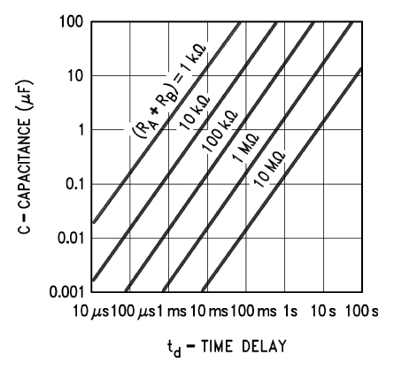
A 100mS pulse should be long enough for most JamMan rhythm out sounds. As long as the 555 pulse is longer than the input sound/beep/etc. it should work ok.
You could also use the following online calculator:
http://www.circuitsgallery.com/2012/11/555-monostable-calculator.html
the LED with the resistors Rled, Rbase and NPN transistor Q1 are optional.
Rled value depends from the type of LED used.
Rbase depends on the type of transistor. I’ve used a general purpose 2n3904 with a 1K Rbase resistor if I remember correctly. (I only had the circuit on a breadboard and have taken it apart a while ago).
You could probably omit the transistor and Rbase and just connect the LED and Rled directly to the 555 timer output, because it can sink up to 200mA (according to the datasheet). So that’s more than enough to drive the LED and the opto-coupler internal LED.
Ccv: 0.1uF
Cdc: optional decoupling cap, 0.1 to 10uF should be ok.
SW2: use to send the pulses to the JamMan
TRS jack diodes: 1n4148

well, these optocoupler lt 827 are even harder to find, can I replace them?
Hey Man – I really love your work. Thanks for sharing your knowledge to the World 😀
I am still about collecting all the parts for the 555 timer and I am a little confused about your list. (Maybe that’s because I am really new to this topic etc.) Is there any opportunity that you can give me a fixed list for a working board? Or is there any chance to upload a tutorial on how to build it? I mean if there’s any spare time left …
Cheers and a huge thanks from Berlin
Benjamin
Is there a way to modify the jamman stereo to have a “sync output”? Maybe use the input of this circuit parallel to the tempo LED on the jamman, install a mini 1/8″ stereo jack output, then you can plug that into another jamman stereo to have one sync to the “master” jamman stereo. Kinda simulating what the new Jam sync on the newer jamman solo pedals. I’m just curious how much current is driving that tempo LED already, or if it would cause that circuit to malfunction… Maybe instead of an optoisolated input, use a JFET gate input so current draw wouldn’t be too bad off the LED circuit? It would be interesting to try, but I don’t have the time anymore to really experiment and trace the circuit out in the jamman (or the money to potentially destroy a jamman stereo).