
UPDATE: I modified the first circuit to work with the new code that has an interrupt enabled. See the bottom of the page.
I’ve previously posted two circuits for synchronizing the JamMan, one based on Schmitt triggers and another one using a 555 timer.
This time the circuit syncs the JamMan to an external MIDI clock. The circuit is based on an Attiny85 MCU running at 8MHz (internal oscillator) using the SoftwareSerial.h library included with the Arduino IDE. The circuit+code seems to work good with just midi clock data coming in, without too many other types of messages being received simultaneously, i.e. I’m not sure how it will handle a big stream of midi data, if it will be able to properly discern between clock and other messages.
When the circuit detects midi clock messages on the input it will blink the tempo LED every 1/4 note, i.e. every 24th clock message. Pressing the tap tempo switch will send the 1/4 pulses to the JamMan.
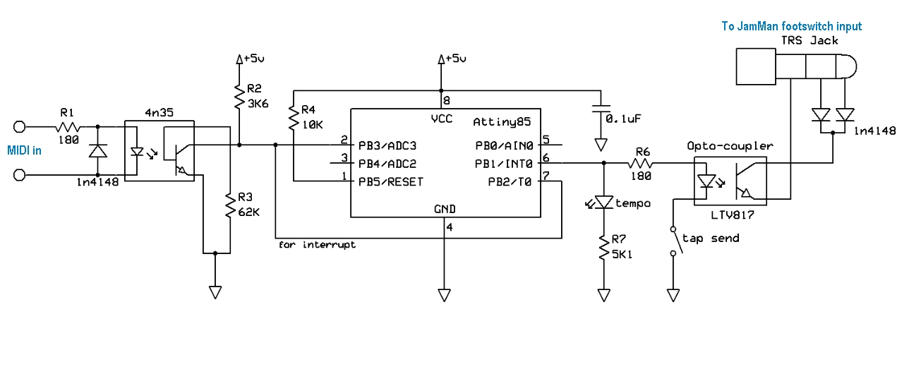
Here’s the 1.0 version of the circuit:

Digitech JamMan stereo looper synchronization to MIDI clock
And the code:
https://gist.github.com/ambinaut/3dfc054652405e5d1872
or:
/* This sketch listens to incoming midi clock messages on port RX and pulses output tempo_pin each quarter note,
i.e. every 24th clock tickWritten for Attiny85 but can be modified for other Atmega, Attiny MCU’s
IMPORTANT! Don’t use pins RX, TX for anything else othar than the SoftwareSerial library
*/#include <avr/io.h> //Include the headers that handles Input/Output function for AVR chips
#include <util/delay.h> //Include the headers that allow for a delay function
#include <SoftwareSerial.h> //Arduino Software Serial library#define F_CPU 8000000UL //Define the speed the clock is running at. Used for the delay.h functions
#define tempo_pin 1 //Physical pin 6, or PB1 on the Attiny85byte midi_msg = 0; //stores incoming midi messages, only 1 byte needed, real time msgs are one byte long
byte clockpulse = 0; //stores current midi clock tick number
unsigned long last_midi_event_time = 0; //time of the last incoming midi eventSoftwareSerial mySerial(3, 4); // RX, TX Physical pins 2, 3
void init_io(void)
{
DDRB |= _BV(tempo_pin); //sets tempo_pin as outputs
PORTB &= ~(_BV(tempo_pin)); //sets the pin to LOW
}int main(void)
{
init_io();
init();
mySerial.begin(31250);while (1) { //endless loop
if (mySerial.available()) {
midi_msg = mySerial.read();
last_midi_event_time = millis();
midi_clk_to_pulse(); //see below
}
//if there’s no more incoming midi for longer than 1000ms, set tempo_pin LOW
else {
unsigned long current_time = millis() – last_midi_event_time;
if (current_time > 1000){
midi_msg = 0xFC; //midi stop message
last_midi_event_time = 0;
midi_clk_to_pulse();
}
}
} //END while (1) – endless (main) loop
}void midi_clk_to_pulse(){
switch(midi_msg) {
case 0xFC: //midi stop message
clockpulse = 0;
PORTB &= ~(_BV(tempo_pin)); //sets tempo_pin to LOW
break;case 0xFA: //midi start message
clockpulse = 0;
PORTB &= ~(_BV(tempo_pin)); //sets tempo_pin to LOW
break;case 0xF8: //midi clock pulse
clockpulse = clockpulse + 1;
switch (clockpulse){
case 1:
PORTB |= (_BV(tempo_pin)); //tempo_pin HIGH
break;case 8:
PORTB &= ~(_BV(tempo_pin)); //tempo_pin LOW
break;case 24: // second quarter begin
PORTB |= (_BV(tempo_pin)); //tempo_pin HIGH
break;case 32:
PORTB &= ~(_BV(tempo_pin)); //tempo_pin LOW
break;case 48: // third quarter begin, middle of the measure
PORTB |= (_BV(tempo_pin)); //tempo_pin HIGH
break;case 56:
PORTB &= ~(_BV(tempo_pin)); //tempo_pin LOW
break;case 72: //fourth quarter begin
PORTB |= (_BV(tempo_pin)); //tempo_pin HIGH
break;case 80:
PORTB &= ~(_BV(tempo_pin)); //tempo_pin LOW
break;case 96:
clockpulse = 0; // resets the clock pulse counter, 96 pulses = 1 measure in 4/4
break; //END case 0xF8:
} // END switch (clockpulse)
break;
} // END switch(midi_msg)
} //END midi_clk_to_pulse()
According to the SoftwareSerial library explanation the Attiny has to run at 8MHz for it to function properly so don’t forget to set the right fuses accordingly. The only thing to take in consideration is that the clock could drift with temperature differences and that might affect serial communication, perhaps even stop it from reading incoming data correctly. I might do another circuit with an external crystal but then the circuit will have to be changed since you need two pins to connect the external crystal.
Any comments or suggestions are welcome,
have fun!
UPDATE: The new code has a sleep function. If there is no MIDI signal going into the input for longer than one sec the Attiny goes into sleep mode to save power. An interrupt on pin7 disables sleep mode when data starts coming in again.
DigiTech JamMan MIDI sync circuit
The code with the added sleep mode:
/*
This sketch listens to incoming midi clock messages on port RX and pulses output tempo_pin each quarter note, i.e. every 24th clock tick
Written for Attiny85 but can be modified for other Atmega, Attiny MCU’s
IMPORTANT! Don’t use pins RX, TX for anything else other than the SoftwareSerial library
*/
#include <avr/io.h> //Include the headers that handles Input/Output function for AVR chips
#include <util/delay.h> //Include the headers that allow for a delay function
#include <SoftwareSerial.h> //Arduino Software Serial library
#include <avr/sleep.h> // Lib for sleep modes
#include <avr/interrupt.h> //Lib for interrupts
#define F_CPU 8000000UL //Define the speed the clock is running at.
#define tempo_pin 1 //Physical pin 6, or PB1 on the Attiny85
byte midi_msg =0;//stores incoming midi messages, only 1 byte needed, real time msgs are one byte long
byte clockpulse =0;//stores current midi clock tick number
unsignedlong last_midi_event_time =0;//time of the last incoming midi event
SoftwareSerial mySerial(3,4);// RX, TX Physical pins 2, 3
void init_io(void)
{
DDRB |= _BV(tempo_pin);//set tempo_pin
PORTB &=~(_BV(tempo_pin));//set the pin to LOW
}
int main(void)
{
init_io();
init();
mySerial.begin(31250);
while(1){//endless loop
if(mySerial.available()){
midi_msg = mySerial.read();
last_midi_event_time = millis();
midi_clk_to_pulse();//see below
}
//if there’s no more incoming midi for longer than 1000ms, set tempo_pin LOW
else {
unsignedlong current_time = millis()– last_midi_event_time;
if(current_time >1000){
midi_msg =0xFC;//midi stop message
last_midi_event_time =0;
midi_clk_to_pulse();
sleep();
}
}
}//END while (1) – endless (main) loop
}
void midi_clk_to_pulse(){
switch(midi_msg){
case0xFC://midi stop message
clockpulse =0;
PORTB &=~(_BV(tempo_pin));//turns tempo_pin off
break;
case0xFA://midi start message
clockpulse =0;
PORTB &=~(_BV(tempo_pin));//turns tempo_pin off
break;
case0xF8://midi clock pulse
clockpulse = clockpulse +1;
switch(clockpulse){
case1:
PORTB |=(_BV(tempo_pin));//tempo_pin HIGH
break;
case8:
PORTB &=~(_BV(tempo_pin));//tempo_pin LOW
break;
case24:// second quarter begin
PORTB |=(_BV(tempo_pin));//tempo_pin HIGH
break;
case32:
PORTB &=~(_BV(tempo_pin));//tempo_pin LOW
break;
case48:// third quarter begin, middle of the measure
PORTB |=(_BV(tempo_pin));//tempo_pin HIGH
break;
case56:
PORTB &=~(_BV(tempo_pin));//tempo_pin LOW
break;
case72://fourth quarter begin
PORTB |=(_BV(tempo_pin));//tempo_pin HIGH
break;
case80:
PORTB &=~(_BV(tempo_pin));//tempo_pin LOW
break;
case96:
clockpulse =0;// resets the clock pulse counter, 96 pulses = 1 measure in 4/4
break;//END case 0xF8:
}// END switch (clockpulse)
break;
}// END switch(midi_msg)
}//END midi_clk_to_pulse()
void sleep(){
GIMSK |= _BV(PCIE); // Enable Pin Change Interrupts
PCMSK |= _BV(PCINT2); // Use PB2 as interrupt pin
ADCSRA &=~_BV(ADEN); // ADC off
set_sleep_mode(SLEEP_MODE_PWR_DOWN); // replaces above statement
sleep_enable(); // Sets the Sleep Enable bit in the MCUCR Register (SE BIT)
sei(); // Enable interrupts
sleep_cpu(); // sleep
cli(); // Disable interrupts
PCMSK &=~_BV(PCINT2); // Turn off PB2 as interrupt pin
sleep_disable(); // Clear SE bit
ADCSRA |= _BV(ADEN); // ADC on
sei(); // Enable interrupts
}// sleep
