
Here is a circuit that generates a pulse that can be used with the JamMans foot-switch input (tempo tap) to set the tempo. It’s simpler than the circuit based on Schmitt triggers from here: https://ambinaut.wordpress.com/2014/01/09/synchronizing-a-digitech-jamman-stereo-to-an-arion-um-70-metronome/

R1, R4: depends on the opto-coupler. I’ve use an LT827 and 180 Ohm resistors.
D1: 1n4148 or just about any kind of diode.
SW1: optional switch for manual tempo tapping.
R2: Value is not critical, I’ve used a 10K resistor.
Rt and Ct values depend on the desired pulse length. You can use the following graph:
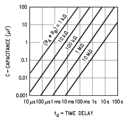
A 100mS pulse should be long enough for most JamMan rhythm out sounds. As long as the 555 pulse is longer than the input sound/beep/etc. it should work ok.
You could also use the following online calculator:
http://www.circuitsgallery.com/2012/11/555-monostable-calculator.html
the LED with the resistors Rled, Rbase and NPN transistor Q1 are optional.
Rled value depends from the type of LED used.
Rbase depends on the type of transistor. I’ve used a general purpose 2n3904 with a 1K Rbase resistor if I remember correctly. (I only had the circuit on a breadboard and have taken it apart a while ago).
You could probably omit the transistor and Rbase and just connect the LED and Rled directly to the 555 timer output, because it can sink up to 200mA (according to the datasheet). So that’s more than enough to drive the LED and the opto-coupler internal LED.
Ccv: 0.1uF
Cdc: optional decoupling cap, 0.1 to 10uF should be ok.
SW2: use to send the pulses to the JamMan
TRS jack diodes: 1n4148
