The following is a small tutorial on how to set low fuse byte to modify the clock speed of a factory fresh Atmega48-20pu microprocessor. Be careful because a mistake could disable the reset pin on the chip and you won’t be able to program it anymore unless you have a high voltage programmer to reprogram the reset pin bit.
I’ve used a cheap USBASP programmer clone bought from Chinese eBay.
First check the initial factory fuse settings with avrdude.exe. From the command line use a variation (depends from your setup) of the following statement, make sure that you are in the directory where avrdude.exe is located before you run it:
avrdude -B 8.0 -c usbasp -P usb -p m48 -v -v -v –v
-B 8.0 the Bitclock setting is used to slow down the programmer. This is needed because the Atmega48 initially runs at 1MHz and is therefore to slow for the programmer. After you increase the Atmega48 operating frequency you won’t need this option anymore. Values other than 8.0 can be used.
-c usbasp specifies programmer type, I’m using a cheap USBASP v2.0 programmer I got on eBay. Note that many of these USBASP programmers are shipped with older firmware and could give clk and perhaps other errors when you try to program the Atmega48, or other MCU’s. I had to upgrade mine, here is a detailed tutorial: http://www.rogerclark.net/?p=702
-P usb is the connection port of the usb programmer
-p m48 indicates the microchip type, m48 stands for Atmega48
-v -v -v –v is for verbal response i.e. avrdude is going to show what it’s doing
If it’s a brand new un-programmed chip from the factory you should get the following values for the low, high and extended fuse bytes:
avrdude: Device signature = 0x1e9205
avrdude: safemode read 1, lfuse value: 62
avrdude: safemode read 2, lfuse value: 62
avrdude: safemode read 3, lfuse value: 62
avrdude: safemode: lfuse reads as 62
avrdude: safemode read 1, hfuse value: df
avrdude: safemode read 2, hfuse value: df
avrdude: safemode read 3, hfuse value: df
avrdude: safemode: hfuse reads as DF
avrdude: safemode read 1, efuse value: 1
avrdude: safemode read 2, efuse value: 1
avrdude: safemode read 3, efuse value: 1
avrdude: safemode: efuse reads as 1
avrdude: safemode: Fuses OK
If you get some other values it does not really matter unless there is a fuse setting that won’t allow further fuse programming, e.g. if the SPIEN (Table 28-6, Bit no. 5) fuse has been set to 1*, i.e. un-programmed, which means that you won’t be able to use SPI to program the chip anymore and you’ll need a parallel programmer to reprogram the SPIEN fuse.
* Fuse programming uses inverted logic, i.e. 0 = Yes, programmed and 1 = No, un-programmed.
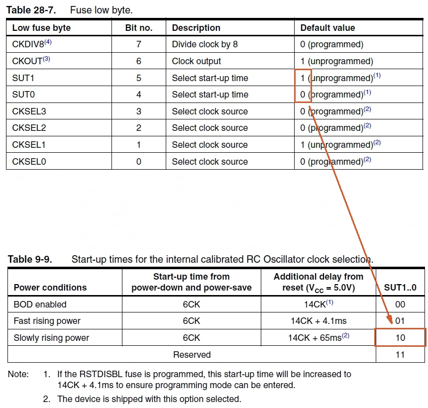
As you can see the low fuse byte has a hexadecimal value of 62 which in binary is 01100010, this is the initial factory setting as shown in Table 28-7.
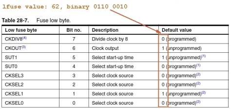
Bit no. 7 (CKDIV8) divides the frequency of the currently selected clock source (Bits no. 0 – 3) by 8. The initial clock source ist the internal RC oscillator set at 8.0MHz., so CKDIV8 is reducing the Atmegas speed to 1MHz.
Bit no. 6 (CKOUT) allows the system clock to be output on PORTB0.
Bits 5 and 4 (SUT 1, 0) select the start-up time of the chip. Table 9-9 on page 34 of the datasheet shows us that the initial fuse setting 10 selects the „slowly rising power“ option.
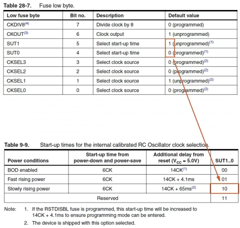
Bits 3- 0 (CKSEL 3 – 0) select the clock source. The initial value of 0010 corresponds to the calibrated internal RC oscillator (see Table 9-1, p. 28 and Table 9-8, p. 34).
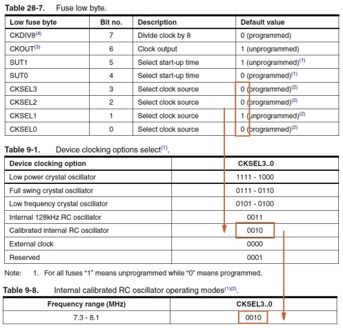
Now we’ll use another command line statement to change the values in the low fuse byte. First let’s disable the clock divider, i.e. unprogram Bit no. 7 (CKDIV8), set it to 1. We just need to change the fuse low byte value from 0110 0010 to 1110 0010, or from 0x62 to 0xE2 in hexadecimal. This is the command line statement:
avrdude -c usbasp -p m48 -B 8 -v -v -v -v -U lfuse:w:0xe2:m
-U lfuse:w:0xe2:m tells avrdude to write 0xe2 to the fuse low byte.
When you run this you should get text feedback in the command line window.
Now try to read the fuses again:
avrdude -B 8.0 -c usbasp -P usb -p m48 -v -v -v –v
you should get:
avrdude: Device signature = 0x1e9205
avrdude: safemode read 1, lfuse value: e2
avrdude: safemode read 2, lfuse value: e2
avrdude: safemode read 3, lfuse value: e2
avrdude: safemode: lfuse reads as E2
avrdude: safemode read 1, hfuse value: df
avrdude: safemode read 2, hfuse value: df
avrdude: safemode read 3, hfuse value: df
avrdude: safemode: hfuse reads as DF
avrdude: safemode read 1, efuse value: 1
avrdude: safemode read 2, efuse value: 1
avrdude: safemode read 3, efuse value: 1
avrdude: safemode: efuse reads as 1
avrdude: safemode: Fuses OK
As you can see only the low fuse byte was changed.
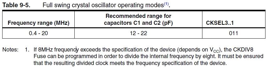
Now let’s select an external crystal oscillator as the clock source. As an example lets take a 16MHz crystal, according to Table 9-1, p.28 we can choose between two settings:
1. Low power crystal oscillator
2. Full swing crytal oscillator
In my case I want to use the Atmega48 with an external PSU so I need not worry about power consumption so I will choose the second setting. The frequency range is 0.4 – 20MHz. Note that the Full Swing Crystal Oscillator will only operate for VCC = 2.7V – 5.5V.
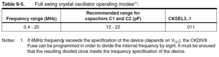
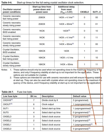
According to Table 9-1, there are two settings for the Full Swing Crystal Oscillator, 0111 and 0110, the only difference is in CKSEL0 bit, i.e. Bit no. 0 of the fuse low byte (Table 28-7).
We’ll use slow rise power setting so CKSEL0 to 1 and SUT 1, 0 to 11, as seen in Table 9-6, p.32.
So we’ll need to change the fuse low byte to 0b11110111 or 0xF7 in hexadecimal. The command line statement fort hat is:
avrdude -c usbasp -p m48 -B 8 -v -v -v -v -U lfuse:w:0xF7:m
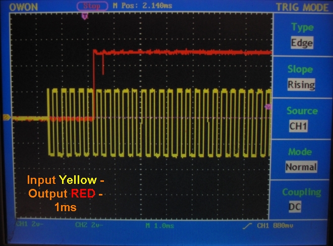
From now on the Atmega48 will be using the external crystal oscillator to run at 16MHz. If needed you can always reprogram the chip to run at other frequencies.
Binary | Hex (precede with 0x)
0000 | 0
0001 | 1
0010 | 2
0011 | 3
0100 | 4
0101 | 5
0110 | 6
0111 | 7
1000 | 8
1001 | 9
1010 | A
1011 | B
1100 | C
1101 | D
1110 | E
1111 | F Examples:
0110 0100 = 0x64 = 100(in decimal)
1111 1111 = 0xFF = 255(in decimal)
0000 0001 = 0x01 = 1(in decimal)
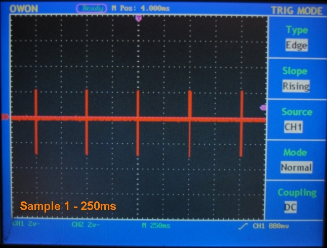
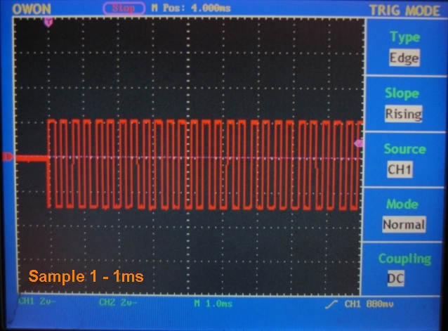
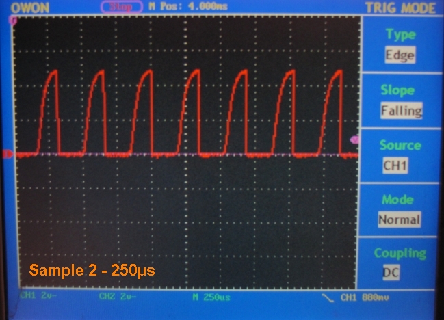
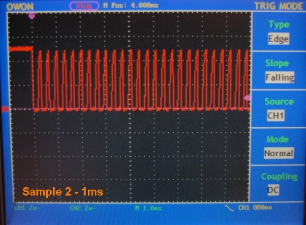
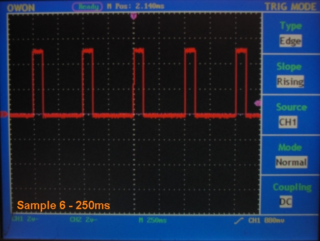
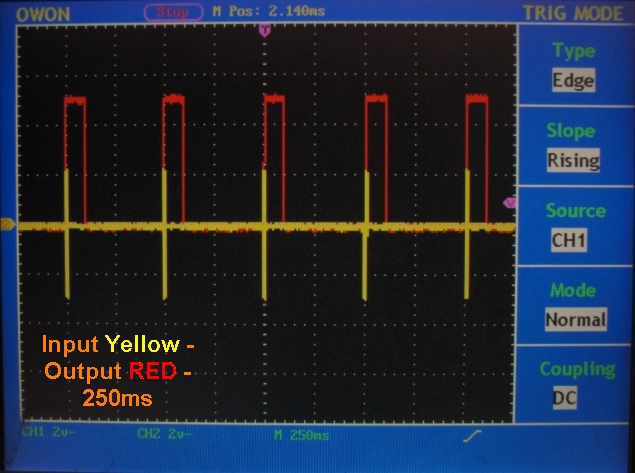
A test sketch that will blink a led on PORTB5 (physical pin 19). The led should blink in one second intervals, i.e. one second ON, one second OFF.
#define F_CPU 16000000UL //Define the speed the clock is running at. Used for the delay.h functions
#include <avr/io.h> //Include the headers that handles Input/Output function for AVR chips
#include <util/delay.h> //Include the headers that allow for a delay function
//Prototypes
void init_io(void);
void init_io(void) //initialize the chip, like void setup() in Arduino
{
DDRB = (_BV(5)); // PORTB5 (physical pin 19) as output
}
int main(void)
{
init_io();
for (;;) { //Loop forever
PORTB ^= (_BV(5)); //invert PORTB5
_delay_ms(1000); //one second delay
}
}
For this code to work with Arduino IDE you’ll need to have the Atmega48 definition in the boards.txt file in the arduino directory.
##############################################################
atmega48_57KBaud_16MHz.name= ATmega48 – 16Mhz
atmega48_57KBaud_16MHz.upload.protocol=avrisp
atmega48_57KBaud_16MHz.upload.maximum_size=4094
atmega48_57KBaud_16MHz.upload.speed=57600
atmega48_57KBaud_16MHz.upload.using=USBasp
atmega48_57KBaud_16MHz.build.mcu=atmega48
atmega48_57KBaud_16MHz.build.f_cpu=16000000L
atmega48_57KBaud_16MHz.build.core=arduino
atmega48_57KBaud_16MHz.build.variant=standard
##############################################################
Hopefully this tutorial has been helpful for you. Suggestions welcomed.